The process of developing apps includes amongst other things the creation of the user interface (UI) and all those simple or complicated views that appear on screen. There are different ways and different approaches to draw a simple “screen” of an app: To use already made graphics by designers, implement the UI in code, use Interface Builder, use a combination of them, and so on. However, there are always times that you need to create custom shaped views programmatically, and if you don’t know how, then problems start to arise.
These problems can be avoided however, by using the UIBezierPath class, which according to the documentation, is what you need to create vector-based paths. In simple words, with this class you can define custom paths that describe any shape, and use those paths to achieve any custom result you want. With it, it’s possible to create from simple shapes like rectangles, squares, ovals and circles to highly complex shapes by adding lines to a path, both straight and curved, between sets of points.
A bezier path that is created by the above class cannot stand on its own. It needs a Core Graphics context where it can be rendered to. There are three ways to get a context like that:
- To use a
CGContextcontext. - To subclass the UIView class which you want to draw the custom shape to, and use its
draw(_:)method provided by default. The context needed is provided automatically then. - To create special layers called
CAShapeLayerobjects.
From all three options, we’ll meet the last two in this tutorial, so we don’t miss our scope with the Core Graphics programming details.
The CAShapeLayer class just mentioned is also a topic of this post, and we’ll see a few things about it. This class inherits from the CALayer, and an object of it is used by the default layer that every view has. Most of the times a shape layer object is added as an additional layer on top of the default one, but it can be also used as a mask. We’ll discuss about both cases later. In addition, we’ll discuss about some of the most important properties of a shape layer object, and what their meaning is.
My goal in this tutorial is to give you practical guidelines on how to create bezier paths and how to use shape layer objects along with them. We’ll meet a series of small, but straight to the point examples, so when you’re through this tutorial you’ll be familiar with the basics of both concepts, and you’ll enable yourself to start thinking about more complex cases after that. If you already possess some knowledge about bezier paths and shape layers, then this tutorial might add something new to that knowledge. If you’re a newcomer to this stuff, then go ahead. You’ll learn some really interesting parts of the iOS development.
Preparing the Project
Let’s get started by creating a new project on Xcode. Unlike most of the other tutorials of mine, this time there’s not a starter project for you to download, but that’s not going to be a problem. In just a few steps we’ll have a project made and configured that way so we can start working on it. So, launch Xcode, and create a new single view application as shown next:
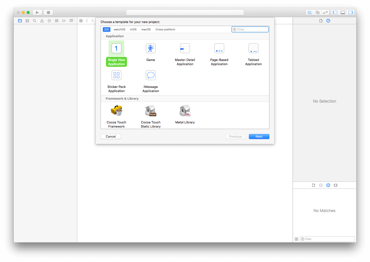
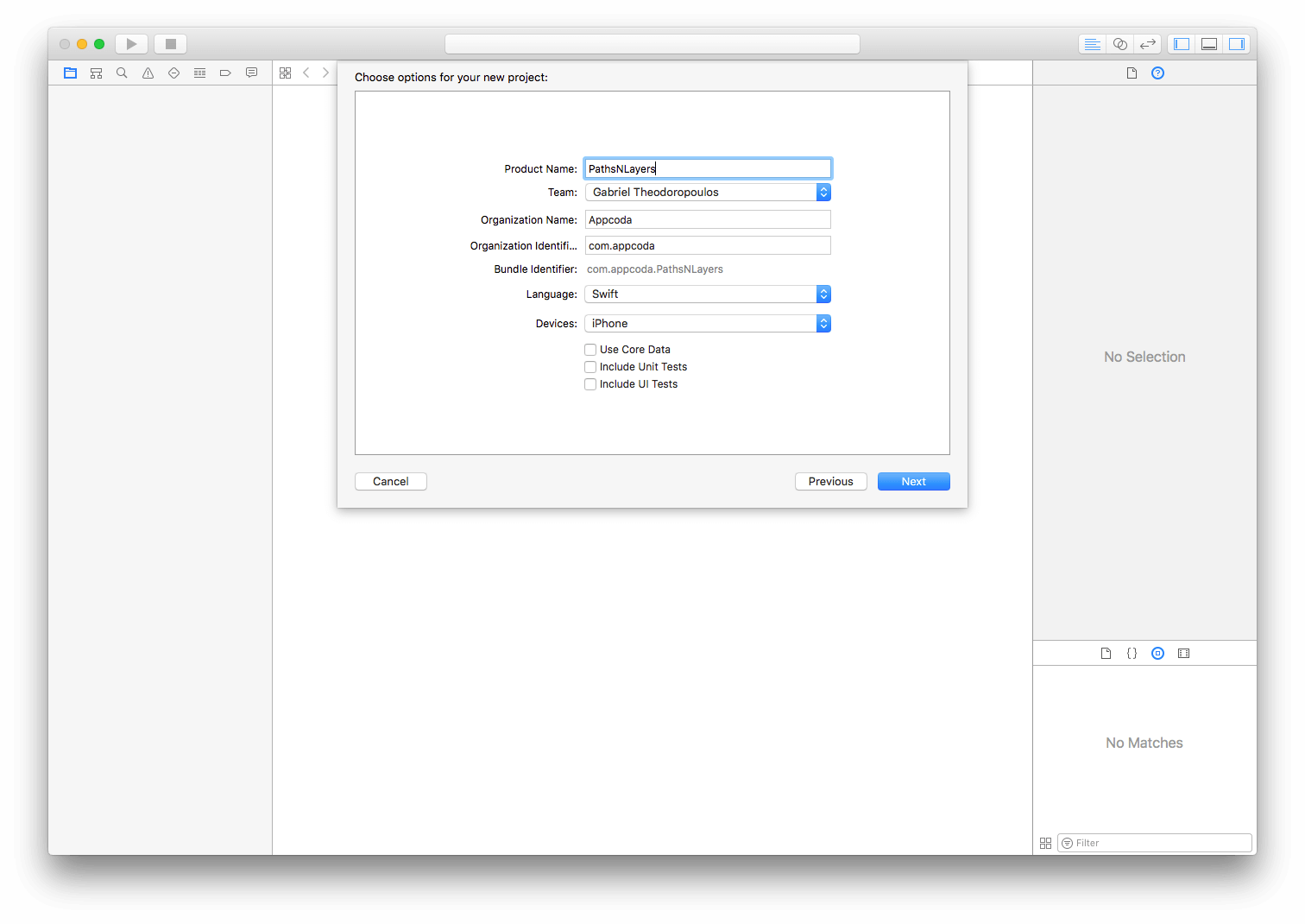
Next, give the project a name. I named it PathsNLayers, but choose another name if you want. Provide the team and organisation information, and make sure it runs on iPhone devices.
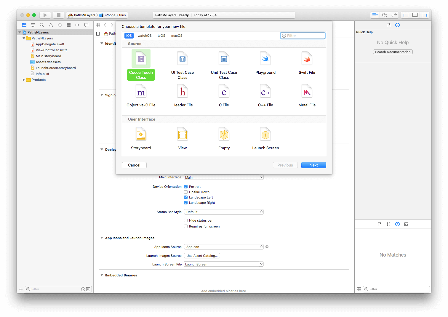
Finally, choose a place on your disk and save it. Once you’re ready, go to the File > New > File… menu, and select the Cocoa Touch Class source:
Make that new file a subclass of the UIView class, and give the name DemoView.
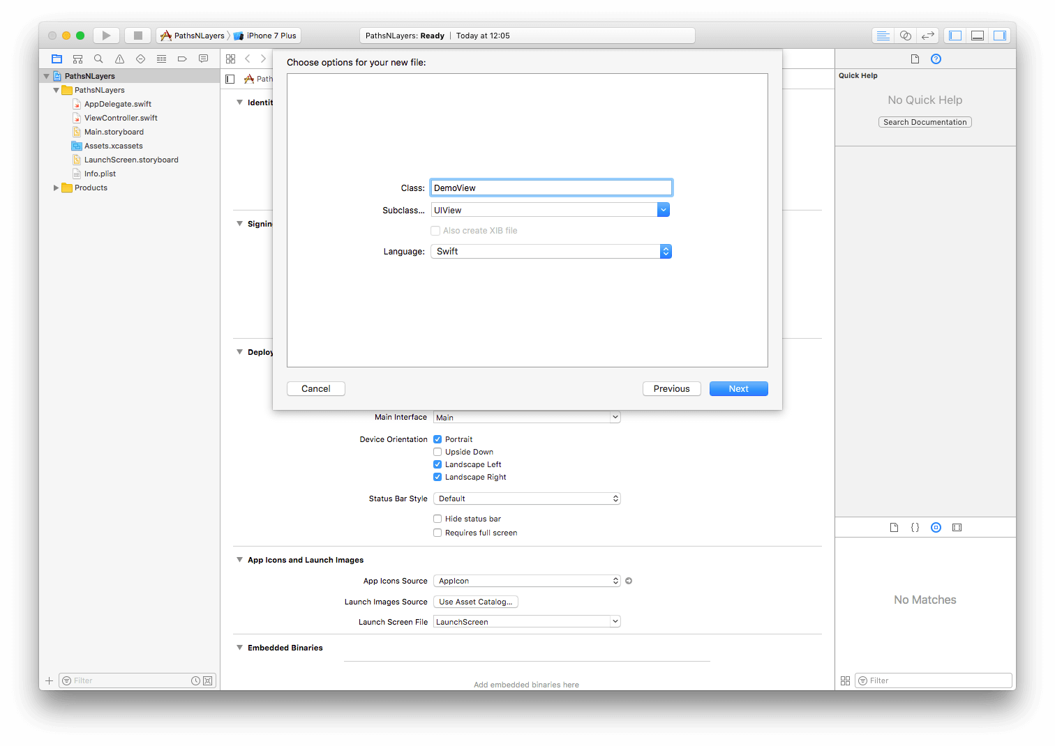
Proceed until the new file is created and added to your project. You should be able to see it in the Project Navigator pane.
Now open the ViewController.swift file, and add the following method:
override func viewDidAppear(_ animated: Bool) {
    super.viewDidAppear(animated)

    let width: CGFloat = 240.0
    let height: CGFloat = 160.0

    let demoView = DemoView(frame: CGRect(x: self.view.frame.size.width/2 - width/2,
                                          y: self.view.frame.size.height/2 - height/2,
                                          width: width,
                                          height: height))

    self.view.addSubview(demoView)
}
Finally, open the DemoView.swift file, and add the next code inside the class body:
var path: UIBezierPath!

override init(frame: CGRect) {
    super.init(frame: frame)

    self.backgroundColor = UIColor.darkGray
}

required init?(coder aDecoder: NSCoder) {
    super.init(coder: aDecoder)
}
The ground that we’ll step on is now ready, so let’s go straight ahead to create our first bezier path.
Creating Paths and Shapes
They say that the best way to learn swimming is to just jump into the water, and I believe that the same principle applies when working with bezier paths too. So, with no much talking we’ll start seeing specific examples that will make clear how UIBezierPath objects can be created, configured and used. Actually, we’ll create a number of paths, where each one will result to a different kind of shape. Get ready, take a deep breath, and open the DemoView.swift file. We’ll make all the implementation that follows to this class.
Rectangular Shapes
We’ll begin with something simple, however quite instructive:
func createRectangle() {
    // Initialize the path.
    path = UIBezierPath()

    // Specify the point that the path should start get drawn.
    path.move(to: CGPoint(x: 0.0, y: 0.0))

    // Create a line between the starting point and the bottom-left side of the view.
    path.addLine(to: CGPoint(x: 0.0, y: self.frame.size.height))

    // Create the bottom line (bottom-left to bottom-right).
    path.addLine(to: CGPoint(x: self.frame.size.width, y: self.frame.size.height))

    // Create the vertical line from the bottom-right to the top-right side.
    path.addLine(to: CGPoint(x: self.frame.size.width, y: 0.0))

    // Close the path. This will create the last line automatically.
    path.close()
}
The above creates a rectangle shape that will surround our view, but it still has no effect as we haven’t provided a context for the path where it’ll be rendered to. We’ll do that later.
First, let’s have a detailed look at what all these lines do:
- At first, we initialise a
UIBezierPathobject. There are various initialisers that this class provides and accept different number and kind of parameters, but for now that simple one is all we need. With the path object prepared, the first thing we always must do is to define a point that the shape will start to be drawn from. That point is expressed as aCGPointvalue, and themove(to:)method tells to the path what that point is. In our sample code, the coordinates (0.0, 0.0) mean the top-left corner of our view. -
The next thing we want, is to create a line between the starting point and another one that we must specify. We provide that point, and at the same time we instruct the system to draw a line by using the
addLine(to:)method. Like the previous one, this method accepts aCGPointvalue as an argument too, which obviously is the second point that we want to connect using the line to the first one. That line starts from the top-left corner and ends to the bottom-right corner of the view. -
The following two commands are at the same logic like the previous one, and they connect points using lines. With the fourth line of code, we add a line to our path that connects the bottom-left to the bottom-right side corners of the view. The fifth line of code draws a new line from the bottom-right to the top-right.
-
So far, we’ve drawn three out of four sides of the rectangle. As it would be reasonably expected, we should add one more line to finish our shape. However, that’s not necessary to do; by calling the
close()method (last line in the code snippet) we declare the end of the path, and the system will automatically draw the missing line for us.
Easy, right? All we did was to connect the dots and create lines from point to point. Now, the above method must be used, and the place to do that is the draw(_:) method of the DemoView class, which will provide a context for the path:
override func draw(_ rect: CGRect) {
    self.createRectangle()
}
Before we test what we’ve done so far, let’s make it more interesting by setting a fill and a stroke colour. The fill colour covers the entire shape with the colour we choose, while the stroke paints the border of the shape. Adding a few more lines to the above:
override func draw(_ rect: CGRect) {
    self.createRectangle()

    // Specify the fill color and apply it to the path.
    UIColor.orange.setFill()
    path.fill()

    // Specify a border (stroke) color.
    UIColor.purple.setStroke()
    path.stroke()
}
All these are really straightforward, so we can run and see the results of our bezier path. Here’s what you should see by running the app now:
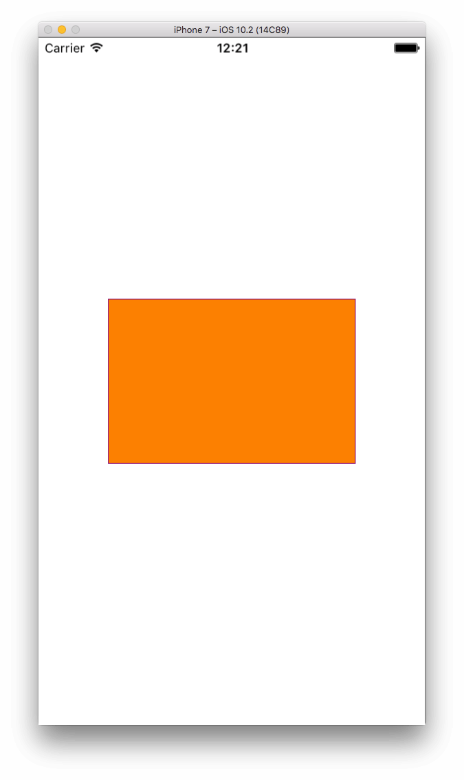
Congratulations, that was your first bezier path! However, it’s a little bit pointless to draw a shape just to outline the exact frame of the view, as you can achieve the same result by setting the background colour of the view and adding a border to the layer, which is easier. But it doesn’t matter; what we did here was the best kickstart for us! Now we know the basics, and we can move on to see more advanced cases.
Triangles
As you might guess, creating any shape that is made just by adding lines to the path is a matter of specifying the proper points. You can create from single shapes to polygons, as long as the given points to the path are the proper ones. In this spirit, let’s create this time a triangle shape:
func createTriangle() {
    path = UIBezierPath()
    path.move(to: CGPoint(x: self.frame.width/2, y: 0.0))
    path.addLine(to: CGPoint(x: 0.0, y: self.frame.size.height))
    path.addLine(to: CGPoint(x: self.frame.size.width, y: self.frame.size.height))
    path.close()
}
The starting point here is the top-center point of the view. The above code is similar to the previous one in the createRectangle() method, we’ve only changed the points and number of lines created. The result is this:
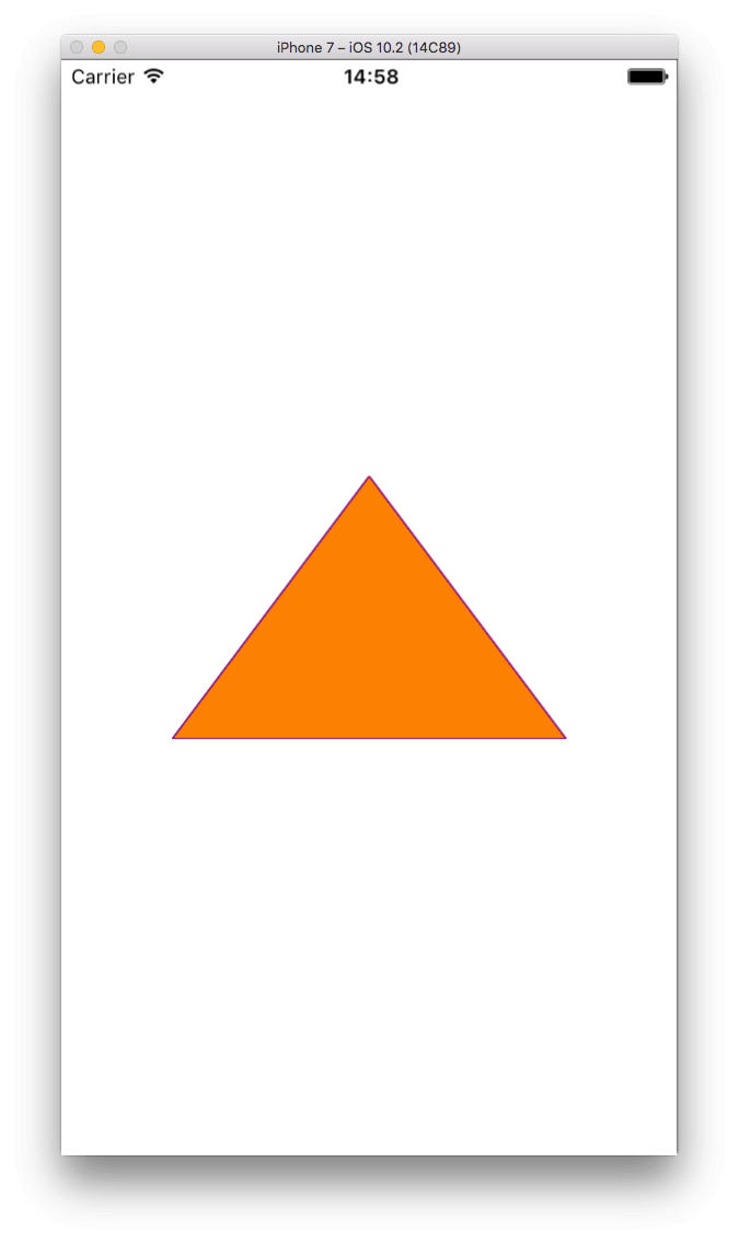
Don’t forget to call the above method in draw(_:):
override func draw(_ rect: CGRect) {
//    self.createRectangle()
    self.createTriangle()

    // Specify the fill color and apply it to the path.
    UIColor.orange.setFill()
    path.fill()

    // Specify a border (stroke) color.
    UIColor.purple.setStroke()
    path.stroke()
}
Try to play with the starting point and the added lines. Different parameters lead to different results.
Ovals and Circles
Creating oval shapes is easy, and all we really need is to use a different initialiser method for our path, other than the simple UIBezierPath(). Look at the following simple example, where we’re using a different initializer and we’re providing our view’s bounds as the frame for the shape:
override func draw(_ rect: CGRect) {
    // self.createRectangle()
    // self.createTriangle()

    // Create an oval shape path.
    self.path = UIBezierPath(ovalIn: self.bounds)

    ...
}
The above results to the following:
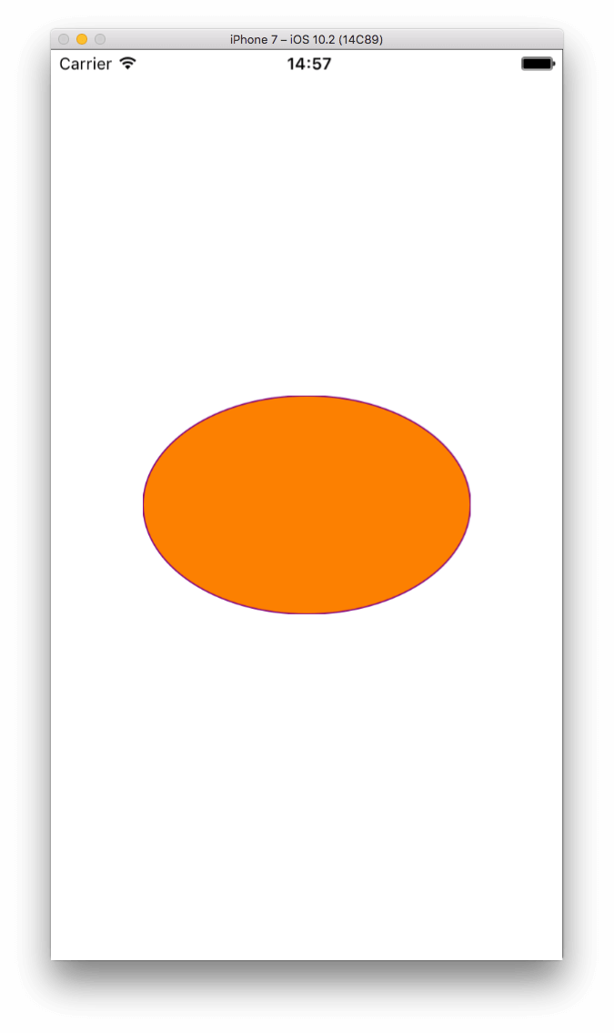
By changing the frame, we can affect the resulting path and draw that way any size of oval shapes. Apparently, you don’t always have to use the view’s bounds as the parameter value; you can provide a frame that it’s just a part of the view.
An interesting case is how we turn an oval shape into a circle. Here it is:
override func draw(_ rect: CGRect) {
    // self.createRectangle()
    // self.createTriangle()

    // Create an oval shape path.
    //self.path = UIBezierPath(ovalIn: self.bounds)
    self.path = UIBezierPath(ovalIn: CGRect(x: self.frame.size.width/2 - self.frame.size.height/2,
                                            y: 0.0,
                                            width: self.frame.size.height,
                                            height: self.frame.size.height))

    ...
}
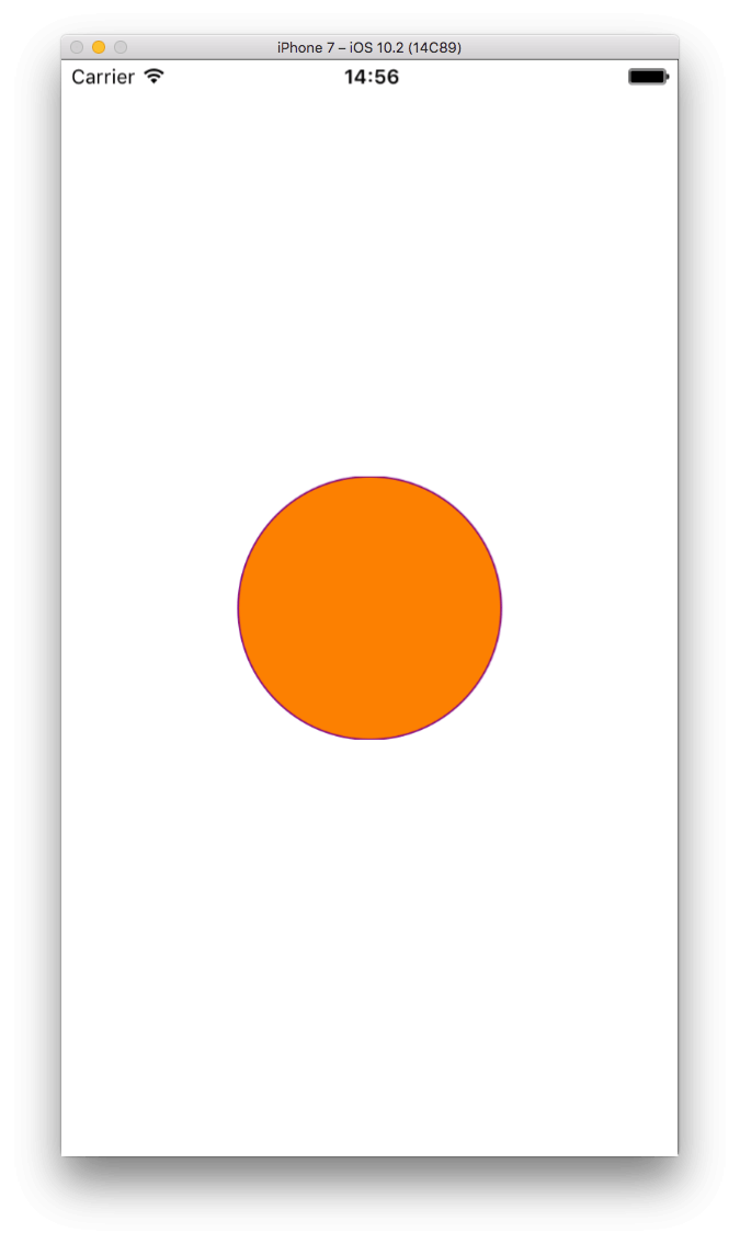
Notice that the width and height of the new oval shape become equal (in this case, equal to the view’s height), and this is what makes the shape a circle. Also, note that in this example, the center of our circle matches to the center of the view.
Rectangles with Rounded Corners
One of the most basic things that all iOS developers know is how to apply rounded corners to a view using a command similar to the next one:
view.layer.cornerRadius = 15.0
That’s the easiest way to round the corners, but the above unfortunately won’t have any effect if you create a bezier path on top of the view. There is, however, a solution to that. All you need is to create your path as a rounded rectangle, like it’s shown below:
override func draw(_ rect: CGRect) {
    ...

    path = UIBezierPath(roundedRect: self.bounds, cornerRadius: 15.0)

    ...
}
The above initialiser creates a new rectangular path, and it rounds the corners according to the value you specify in the second parameter. If we test the app, here’s what we get:
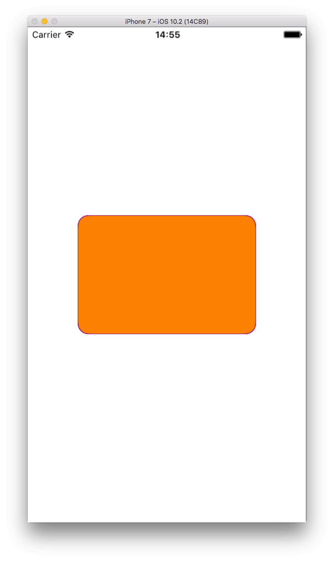
What we just saw is useful, but not as interesting as when we want to round just some of the corners of the rectangle. It’s often required to create custom views with one or more, but not all, the corners rounded, and bezier paths are here to make that task easy. Let’s use an example to see how we can round only the top-left and bottom-right corners of the view:
override func draw(_ rect: CGRect) {
    ...

    path = UIBezierPath(roundedRect: self.bounds,
                        byRoundingCorners: [.topLeft, .bottomRight],
                        cornerRadii: CGSize(width: 15.0, height: 0.0))

    ...
}
That new initialiser we see here takes three parameters:
- The frame of the rectangular shape that will be created.
- The corners that will be rounded. For one corner only, there’s no need to use the array notation, but for more, it’s required as shown above. The values given in this parameter are properties of the UIRectCorner structure, and you can find more information here.
- The corner radius value. This parameter expects a CGSize value, but in truth, just the width is taken into account; the height is just disregarded.
By running our demo app now again, here’s what we see:
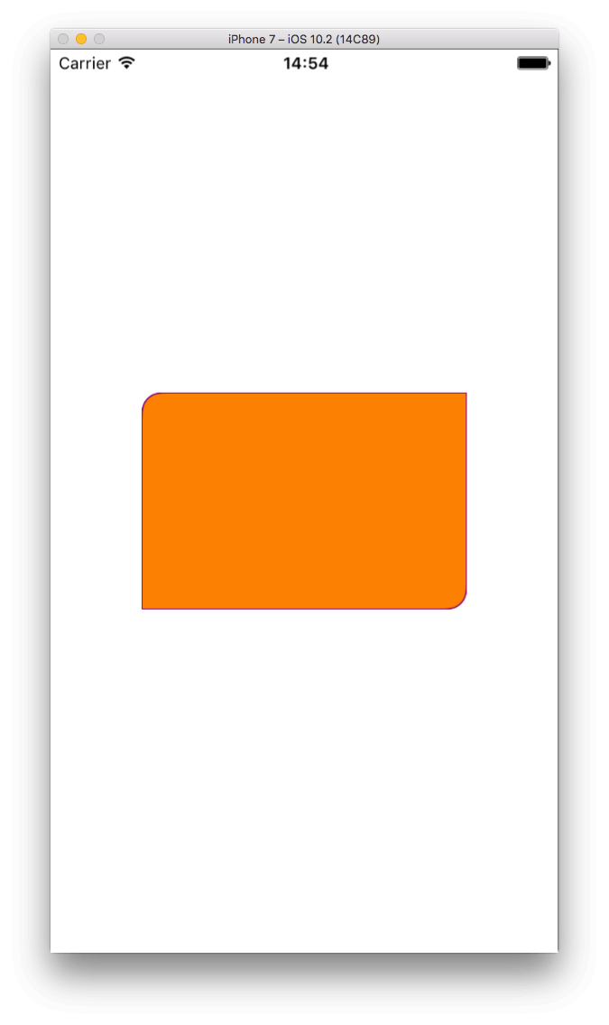
Not bad, as we only had to initialise an object and make part of the corners rounded!
Creating Arcs
For many developers, creating arc bezier paths always seems more complicated than all the other previous case we met so far. And yes, it is more complicated, unless you understand how it works! Trust me, it’s easy.
Let’s see an example first, so we can go through everything step by step. Initially, watch the following screenshot:
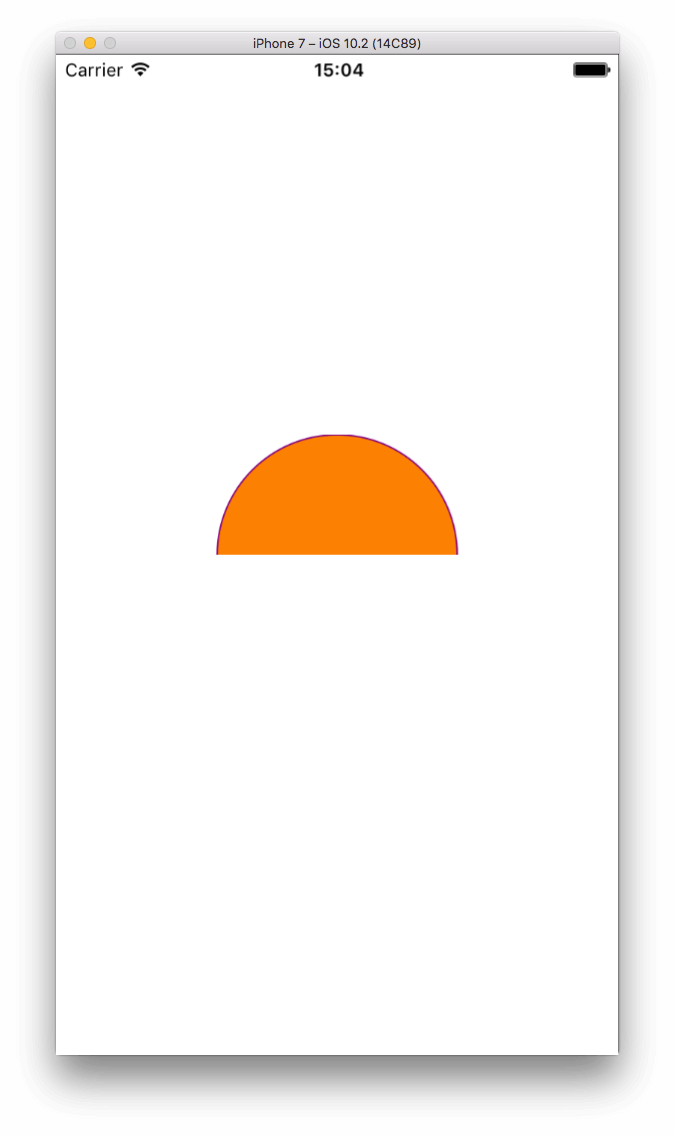
The code that creates that arc shape is this:
override func draw(_ rect: CGRect) {
    ...

    path = UIBezierPath(arcCenter: CGPoint(x: self.frame.size.width/2, y: self.frame.size.height/2),
                        radius: self.frame.size.height/2,
                        startAngle: CGFloat(180.0).toRadians(),
                        endAngle: CGFloat(0.0).toRadians(),
                        clockwise: true)

    ...
}
Let’s see the parameters list one by one:
- arcCenter: An arc is always a part of a circle, so if you visualize the missing part of the circle and draw it entirely in your mind, you can see its center. That center of the imaginary circle is also the center of the arc. In the above example we want our imaginary circle to be included in the frame of our view, so the center of it should also be the center of the view. That parameter value is always a CGPoint value.
- radius: The radius of the circle. As the diameter of our imaginary circle is equal to the view’s height, then the half of it is the radius.
- startAngle: It describes the “starting point” for the arc you’re drawing. We’ll see a few more details both for this and for the endAngle parameter right next, but for now just think of it as the point on the perimeter of the imaginary circle where the arc starts from. The expected value is the angle expressed in radians, and not in degrees. I’ll explain more in a while, and especially about what you’re seeing in the above code.
- endAngle: The “ending point” of the arc that it’s being drawn. Similarly to what I just said about the startAngle, think of it as the point on the perimeter of the imaginary circle where the arc ends.
- clockwise: It’s a boolean value that indicates whether the arc should be drawn in a clockwise direction, or the opposite. The proper combination of this and the previous two parameters leads to the proper arc you want to be drawn.
Let’s talk now a little bit more about the startAngle and endAngle values. To properly understand how they express the starting and ending points respectively of an arc, remember the maths at your school age, and the circle of degrees from the books.
As you recall from your youth, and you also see at the above image, a circle starts at 0 degrees, and follows a counter-clockwise direction until it makes a 360 degrees round and form a complete shape. Based on what we see above, it’s not difficult to draw an arc; you start at any degree A, go to degree B, and finish. You agree, right? Me too, but here’s the secret that will make arcs easy for you: Forget about all that!
In iOS many things are upside down comparing to what we know from the usual math. Take for example the coordinate system: When moving towards bottom in iOS (vertical axis) the Y value is increased, while it gets decreased in a Cartesian coordinate system (math). The same happens with the degrees circle you see above. You have to consider that for iOS a circle starts at 0 degrees (right side like above), but it’s moving in a clockwise direction until it draws a 360 degrees circle:
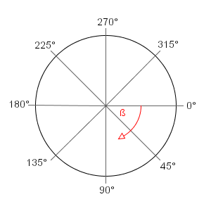
Watching that image, and considering that for our example we started the arc at 180 degrees, finished at 0 degrees, and followed a clockwise direction, it becomes clear how the arc shown in the last screenshot was created.
To make it even more clear, let’s try to create the following arc:
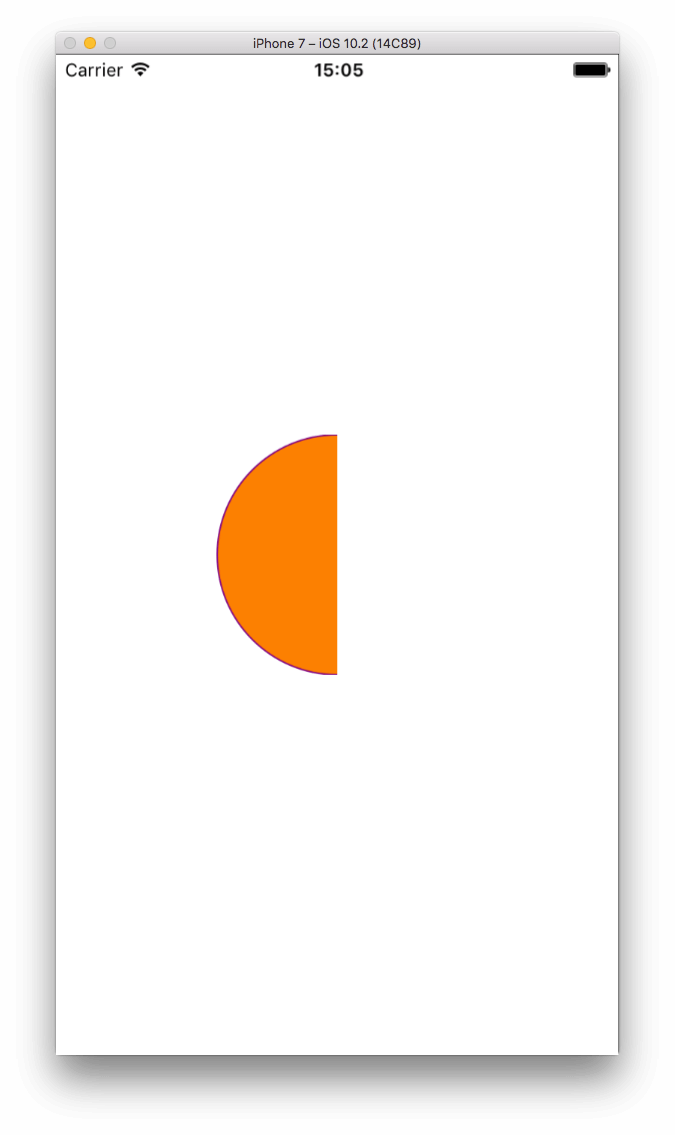
There are two ways to achieve that:
- Either we start from 90 degrees and go to 270 degrees in a clockwise direction according to the degrees circle shown above,
- Or we start from 270 degrees going to 90, and we follow a counter-clockwise direction.
Let’s take the second case, and let’s move in a CCW direction:
override func draw(_ rect: CGRect) {
    ...

    path = UIBezierPath(arcCenter: CGPoint(x: self.frame.size.width/2, y: self.frame.size.height/2),
                        radius: self.frame.size.height/2,
                        startAngle: CGFloat(270.0).toRadians(),
                        endAngle: CGFloat(90.0).toRadians(),
                        clockwise: false)

    ...
}
One last example, to make sure that we fully get it:
override func draw(_ rect: CGRect) {
    ...

    path = UIBezierPath(arcCenter: CGPoint(x: self.frame.size.width/2, y: self.frame.size.height/2),
                        radius: self.frame.size.height/2,
                        startAngle: CGFloat(240.0).toRadians(),
                        endAngle: CGFloat(15.0).toRadians(),
                        clockwise: false)

    ...
}
That results to:
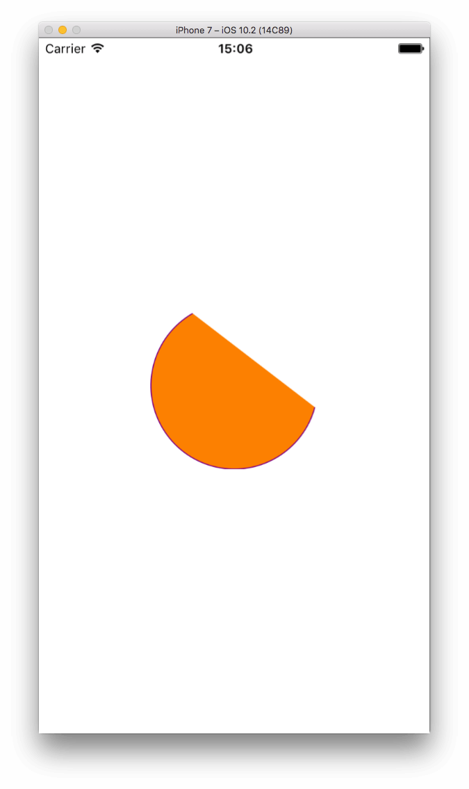
And a few words now about the start and end angle values. We all know that an angle is expressed either in degrees, or in radians. The two respective parameters in the above initializer expect radian values, but for us as humans it’s easier to think in degrees. For that reason, I provide you with the following CGFloat extension that performs the conversion from degrees to radians, and that was used it in the last three examples:
extension CGFloat {
    func toRadians() -> CGFloat {
        return self * CGFloat(M_PI) / 180.0
    }
}
With this extension, you can easily have the respective radians value from any CGFloat number that expresses an angle in degrees, similarly to what you’ve seen in the start and end angle parameter values in the previous examples.
Bezier Paths and CAShapeLayer
As we’ve seen in the previous examples, the draw(_:) method in an UIView subclass provides a context for the bezier path that will be drawn. However, it’s not always necessary to override that method to perform custom drawing, and actually, you should avoid it if possible, as it has impact to the performance. A good alternative is using CAShapeLayer objects, which are rendered much faster and you have additional flexibility by using them.
As said in the beginning of this post, a CAShapeLayer is a CALayer subclass, and by creating and using such objects we actually add extra layers to a view. It has several properties that can be set for customising the final outcome of a view, and most of them are animatable, meaning that their values can be changed using animated manners (for example, CABasicAnimation). Animations consist of a big chapter in layers, and we won’t see them in this post; maybe it’ll consist of another tutorial at some point.
When creating a CAShapeLayer object, it’s necessary to specify its shape, or in other words its path. The most easy way to set that path is by creating a bezier path first, and then assigning it to the shape layer object. As this is the most usual approach, we’ll use it in the following examples.
Except for specifying the path, there are other properties that can be set, and usually should be set, too. For example, the fill colour, stroke colour, line width, and position are just some of them, and we’ll see them all in action. Also, there are two ways that a shape layer object can be used in the layer of a view: As a sublayer, or as a mask. We’ll see their difference in a while. Lastly, multiple shape layers can be created and added as sublayers to a layer. However, as the top most layers cover those under them, you should carefully size and position them.
A Simple CAShapeLayer Object
Let’s create our first CAShapeLayer object, but before doing that, make sure to comment out the entire draw(_:) method that we were using previously in the DemoView.swift file. The simplest thing we could do would be this:
func simpleShapeLayer() {
    self.createRectangle()

    let shapeLayer = CAShapeLayer()
    shapeLayer.path = self.path.cgPath

    self.layer.addSublayer(shapeLayer)
}
First off, we call the createRectangle() method implemented in the previous part so we draw a rectangular bezier path. Remember that the path specified in this method is kept to the path property in our class.
Next, we create the shape layer object, which always is as easy as shown above. First we initialise the object, and then we assign the bezier path to its path property. Note though that this property expects a CGPath value, while our path is a UIBezierPath object, so we use the Core Graphics representation of it by just accessing the cgPath property.
Lastly, we add it as a sublayer to the view’s layer. For your information, even though this is the most usual way to add a sublayer, in case you have many of them you could use any of the next methods that the CALayer class provides:
insertSublayer(_:at:)
insertSublayer(_:above:)
insertSublayer(_:below:)
Read more about them here, here and here respectively.
Now, let’s call this method and let’s run the app to see the results (note that we change the background colour of the view from “clear” to dark gray):
override init(frame: CGRect) {
    super.init(frame: frame)

    self.backgroundColor = UIColor.darkGray

    simpleShapeLayer()
}
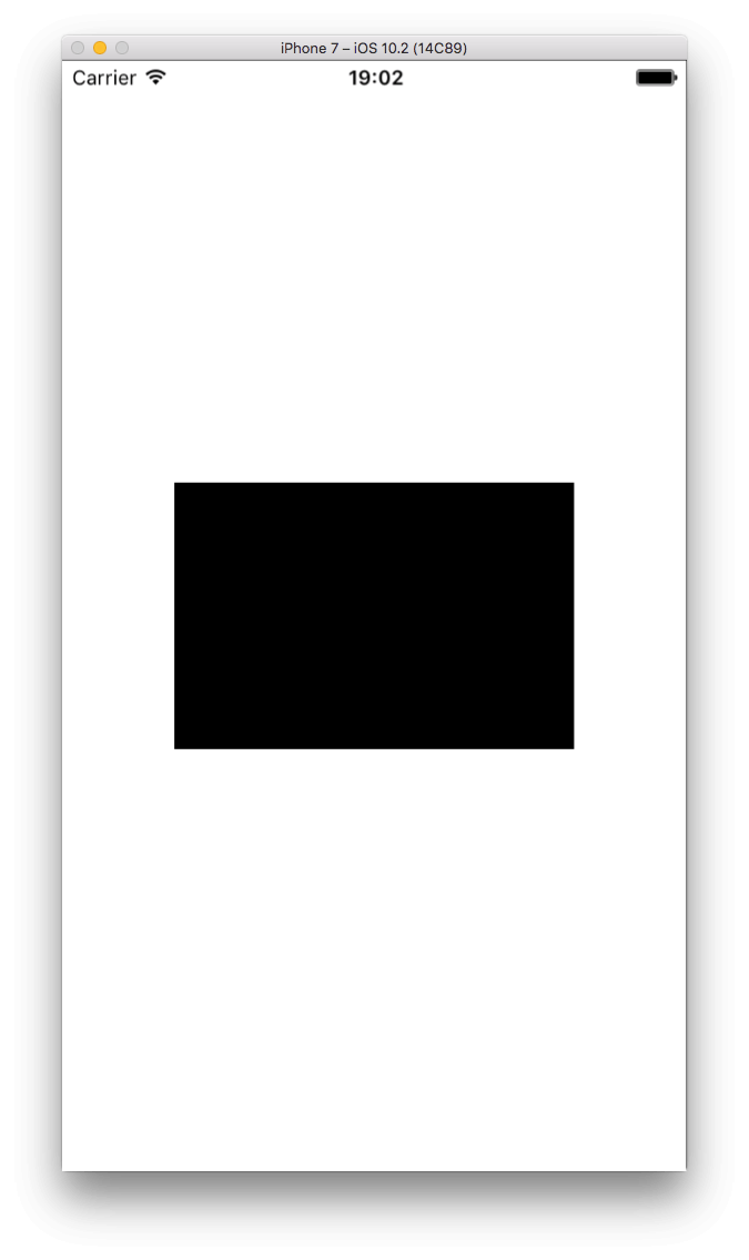
You see, if we don’t specify a fill colour for the shape layer, black will be used as the default one. Let’s set one now, and also let’s play with a couple more properties: The stroke colour and the line width:
func simpleShapeLayer() {
    ...

    shapeLayer.fillColor = UIColor.yellow.cgColor
    shapeLayer.strokeColor = UIColor.brown.cgColor
    shapeLayer.lineWidth = 3.0

    self.layer.addSublayer(shapeLayer)
}
Notice that both the fillColor and strokeColor properties are expecting for a CGColor value, that’s why we’re “converting” our UIColor objects to CGColor by accessing the cgColor properties of them. By using the lineWidth property we can specify the thickness of the border line.
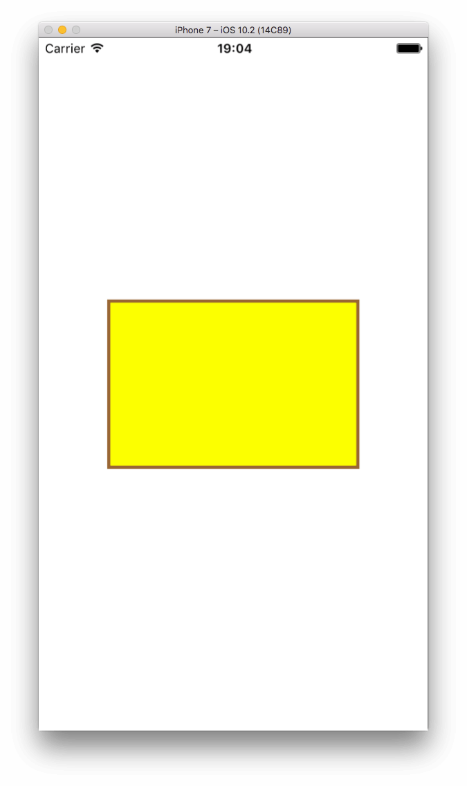
Mask or Sublayer?
A shape layer can be used in two different ways: As a mask to the default layer of the view, or to be added as a sublayer to it (like what we did above). But what’s the real difference between these two ways, and how should we decide which one we need to use?
Going by the example once again, let’s find that out with the following new method:
func maskVsSublayer() {
    self.createTriangle()

    let shapeLayer = CAShapeLayer()
    shapeLayer.path = path.cgPath
    shapeLayer.fillColor = UIColor.yellow.cgColor

    self.layer.addSublayer(shapeLayer)
}
Once again, we’re using a method that we created previously (createTriangle()) so we can just stay into the point. That method draws a path that creates a triangular path, and we’re initializing a new shape layer object to use it. We specify its fill colour, and then we add it as a sublayer to the default layer of the view. Nothing difficult, and nothing new here.
Let’s call this new method, and then let’s see the (pretty much expected) results:
override init(frame: CGRect) {
    ...

    maskVsSublayer()
}
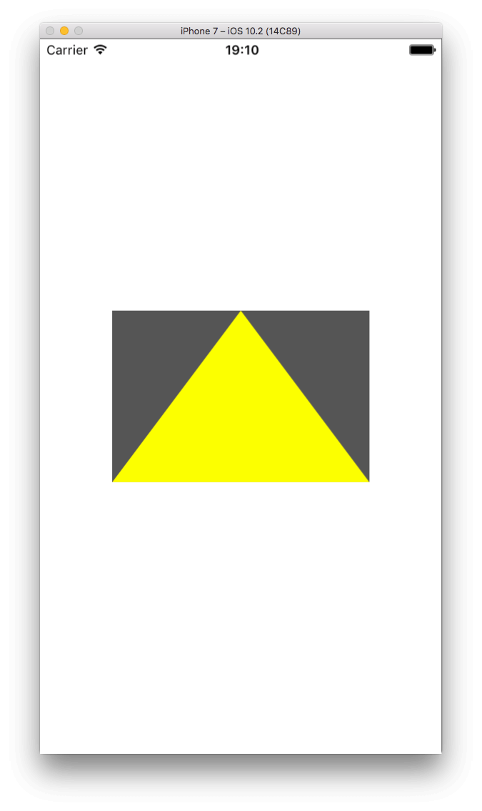
Obviously, our new shape layer is a nice yellow triangle that sits on top of the view, and the part of the view that is not covered by the fill colour remains dark gray.
Let’s perform the following changes now to our method:
func maskVsSublayer() {
    ...

    // self.layer.addSublayer(shapeLayer)

    self.layer.mask = shapeLayer
}
Comment out the addSublayer(_:) method, and use the mask property instead. Then run, and watch:
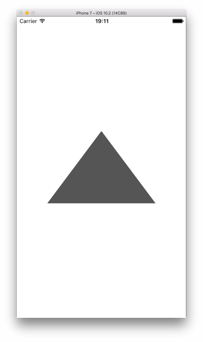
This time there’s just the triangular shape, which is not yellow anymore even though we’ve set the fill colour, but even further the part of the view that is not covered by the path of the shape layer is missing!
Well, this is how the mask works. Any part of the view that is not a part of the path is clipped, and the view actually takes the shape of the shape layer that is applied as a mask. Furthermore, properties like the fill colour have no effect when the new layer is a mask, so if we want to change the colour of the triangle we need to update the background colour of the view:
func maskVsSublayer() {
    ...

    // self.layer.addSublayer(shapeLayer)

    self.backgroundColor = UIColor.green
    self.layer.mask = shapeLayer
}
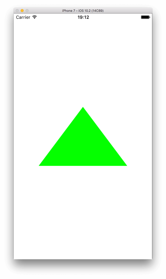
In short, if you want to give your view a custom shape, then use the mask property, otherwise add the new shape layer you create as a sublayer and play with the view’s and layer’s
properties after that to achieve your final purpose.
Not Just One SubLayer
I’ve already said that you can definitely add more than one shape layers as sublayers to a view’s layer, so let’s see a few more things about that. In this part, we’ll create two sublayers and we’ll change a few properties of them, so we display them properly on the view. For starters, let’s create two paths and two shapes:
func twoShapes() {
    let width: CGFloat = self.frame.size.width/2
    let height: CGFloat = self.frame.size.height/2

    let path1 = UIBezierPath()
    path1.move(to: CGPoint(x: width/2, y: 0.0))
    path1.addLine(to: CGPoint(x: 0.0, y: height))
    path1.addLine(to: CGPoint(x: width, y: height))
    path1.close()

    let path2 = UIBezierPath()
    path2.move(to: CGPoint(x: width/2, y: height))
    path2.addLine(to: CGPoint(x: 0.0, y: 0.0))
    path2.addLine(to: CGPoint(x: width, y: 0.0))
    path2.close()

    let shapeLayer1 = CAShapeLayer()
    shapeLayer1.path = path1.cgPath
    shapeLayer1.fillColor = UIColor.yellow.cgColor

    let shapeLayer2 = CAShapeLayer()
    shapeLayer2.path = path2.cgPath
    shapeLayer2.fillColor = UIColor.green.cgColor

    self.layer.addSublayer(shapeLayer1)
    self.layer.addSublayer(shapeLayer2)
}
The above code creates two paths that represent triangular shapes, where the first has the “nose” up, and the second has its “nose” down. This time, we don’t use the entire width and height of the view for paths and shapes, just the half of them. Once both paths are specified, are assigned to the two shape layer objects, which in turn are added as sublayers to the layer of the view.
Calling the above new method:
override init(frame: CGRect) {
    ...

    twoShapes()
}
… and then running it, it gives us this:
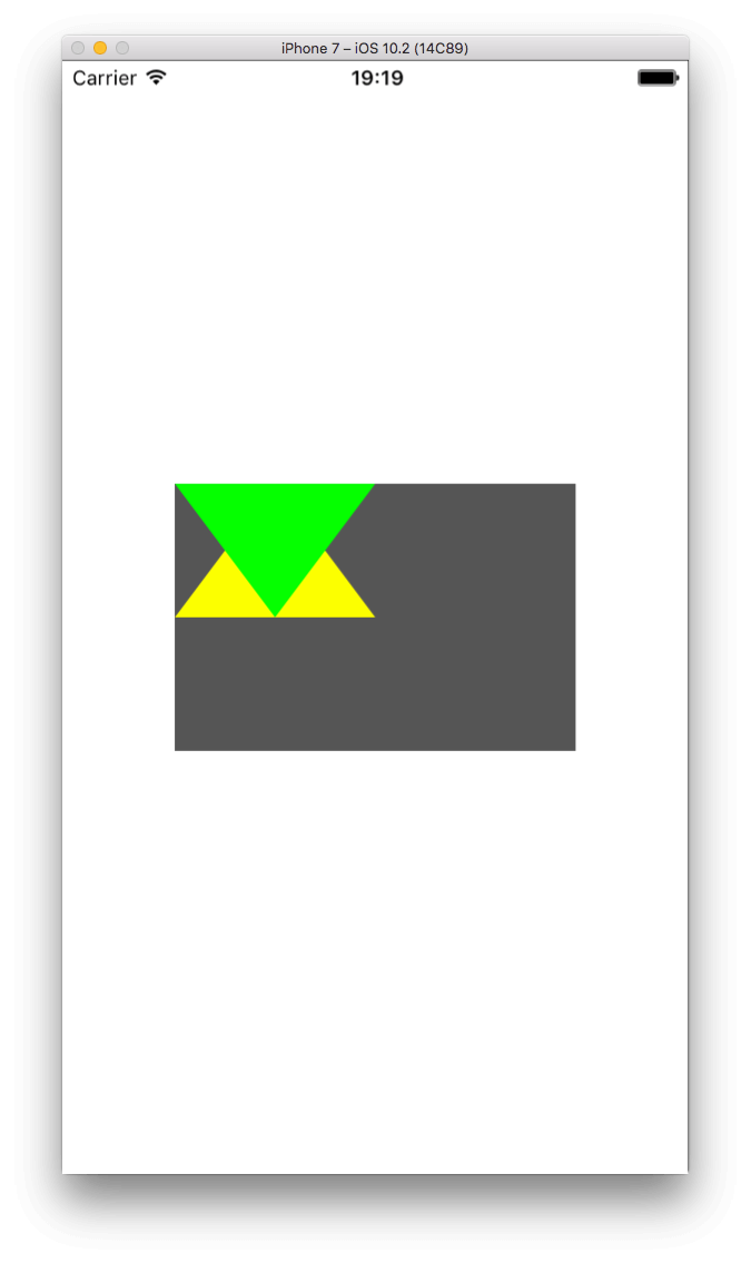
As you see, the second shape layer overlaps the first one, and that doesn’t seem right. So, why don’t we just move it?
func twoShapes() {
    ...

    shapeLayer2.position = CGPoint(x: 0.0, y: height)
}
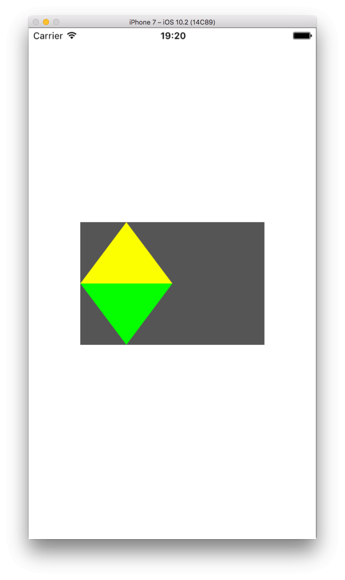
That’s better! The position property that we just used is really important, as it allows us to “move” shape layers around. And what if we want to center both layers? Just replace the above line with the next two:
func twoShapes() {
    ...

    // shapeLayer2.position = CGPoint(x: 0.0, y: height)

    shapeLayer2.position = CGPoint(x: width/2, y: height)
    shapeLayer1.position = CGPoint(x: width/2, y: 0.0)

}
These new lines lead to this:
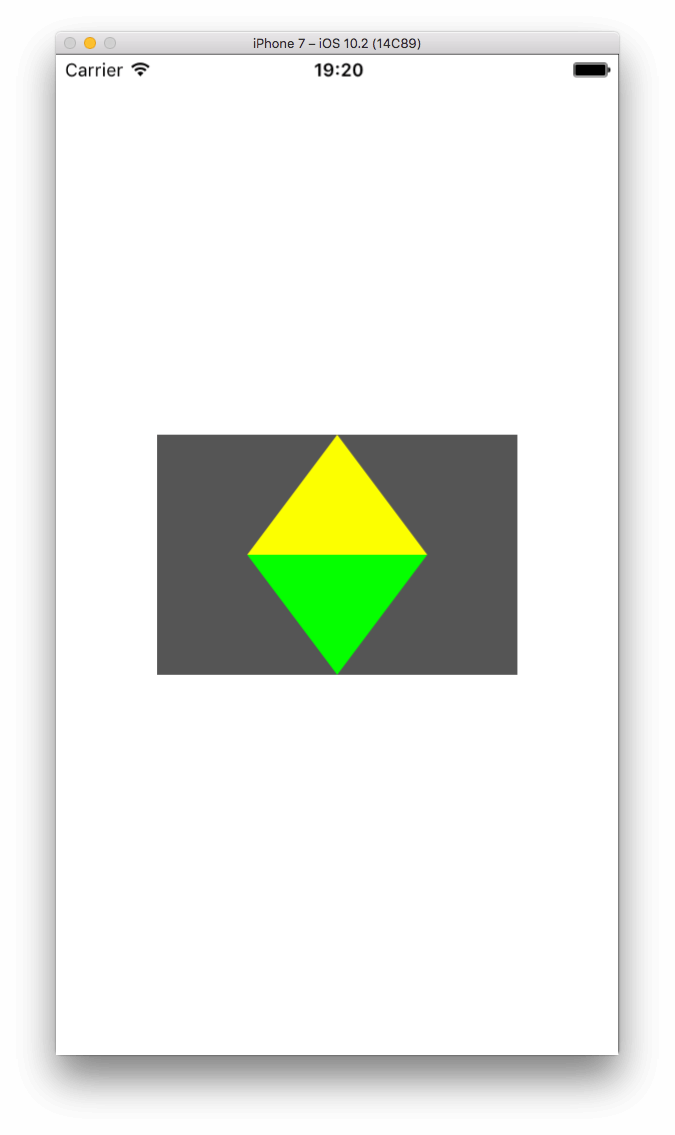
Most of the times, the position property will be good enough to place a shape layer to a different position. However, there will be also times where you’ll be wanting to change the layer’s frame. In that case, and keep that in mind, you shouldn’t access the frame property, but the bounds property of the sublayer.
According to the documentation, the bounds property expresses the origin and size of the sublayer in its own coordinate system. To understand what that means and see how you change the origin or size of the bounds rectangle, let’s make a few changes to our example:
func twoShapes() {
    ...

    shapeLayer1.bounds.origin = CGPoint(x: 0.0, y: 0.0)
    shapeLayer1.bounds.size = CGSize(width: 200.0, height: 150.0)
    shapeLayer1.backgroundColor = UIColor.magenta.cgColor
}
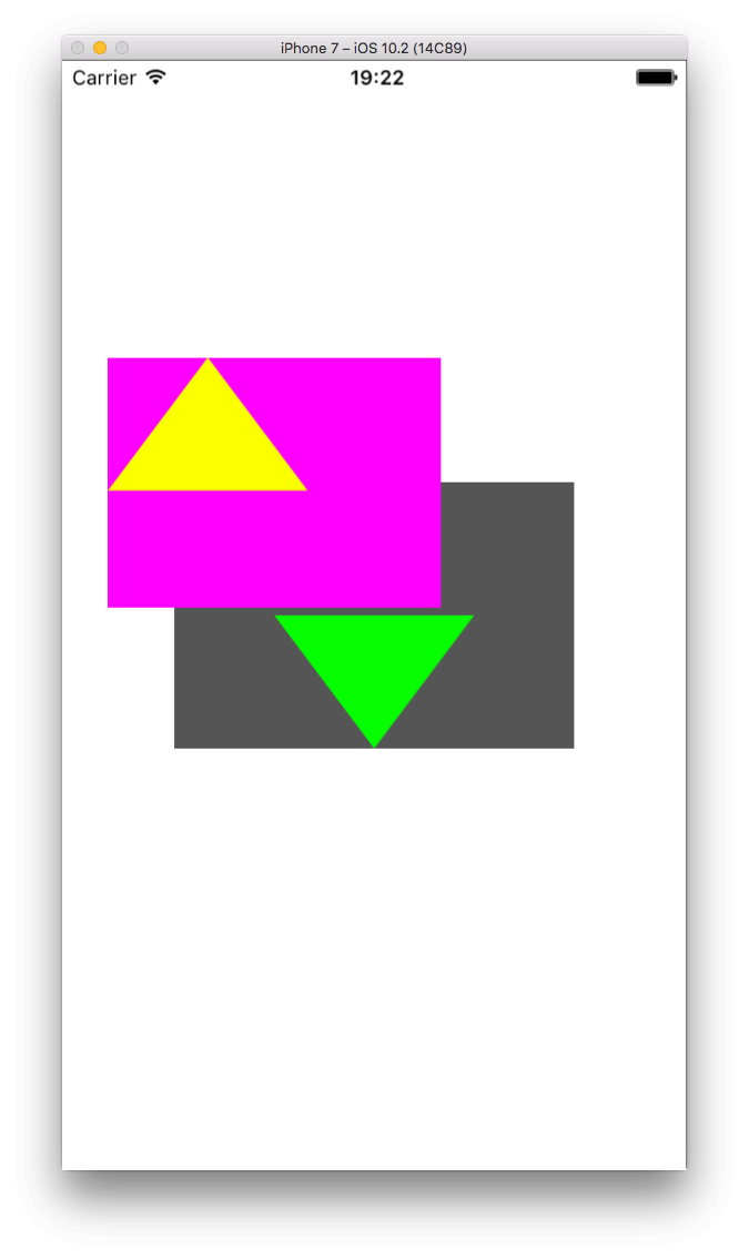
With the above addition we changed the default size of the sublayer, and it’s obviously exceeding the view’s visible space. The drawn path’s size is not affected by that, however if we change the origin the path will move:
func twoShapes() {
    ...

    shapeLayer1.bounds.origin = CGPoint(x: -20.0, y: -40.0)

    ...
}
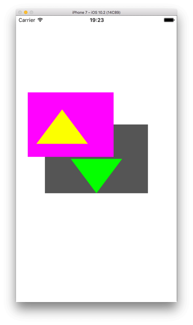
Notice something important: Unlike to the normal view’s coordinates where we move a view to the right by increasing the X value of the origin point, and to the bottom by increasing the Y value, here it’s the opposite that happens. We move the path to the right and bottom by providing negative values. Positive values would move the origin of the path to the left and up respectively. However, most of the times you’ll be needing just to reposition your layer, and probably rarely you’ll have to deal with the bounds.
Combining Paths
When we started discussing about paths in this post, we went through a series of initializers that the UIBezierPath class provides, and we we found out that several types of shapes can be created just by using those initializers. However, we never saw how the various path types are combined together, and now that we’ve talked about shape layers it’s the best time to do so.
Similarly to the addLine(to:) method that we’ve known already and that creates a line between two points, there are other methods that create other kind of shapes, such as arcs and curves.
Let’s take a look at the following example:
func complexShape() {
    path = UIBezierPath()
    path.move(to: CGPoint(x: 0.0, y: 0.0))
    path.addLine(to: CGPoint(x: self.frame.size.width/2 - 50.0, y: 0.0))
    path.addArc(withCenter: CGPoint(x: self.frame.size.width/2 - 25.0, y: 25.0),
                radius: 25.0,
                startAngle: CGFloat(180.0).toRadians(),
                endAngle: CGFloat(0.0).toRadians(),
                clockwise: false)
    path.addLine(to: CGPoint(x: self.frame.size.width/2, y: 0.0))
    path.addLine(to: CGPoint(x: self.frame.size.width - 50.0, y: 0.0))
    path.addCurve(to: CGPoint(x: self.frame.size.width, y: 50.0),
                  controlPoint1: CGPoint(x: self.frame.size.width + 50.0, y: 25.0),
                  controlPoint2: CGPoint(x: self.frame.size.width - 150.0, y: 50.0))
    path.addLine(to: CGPoint(x: self.frame.size.width, y: self.frame.size.height))
    path.addLine(to: CGPoint(x: 0.0, y: self.frame.size.height))
    path.close()

    let shapeLayer = CAShapeLayer()
    shapeLayer.path = path.cgPath

    self.backgroundColor = UIColor.orange
    self.layer.mask = shapeLayer
}
Call the above in the init(frame:) method:
override init(frame: CGRect) {
    ...

    complexShape()
}
Then run it and watch at the shape that it produces:
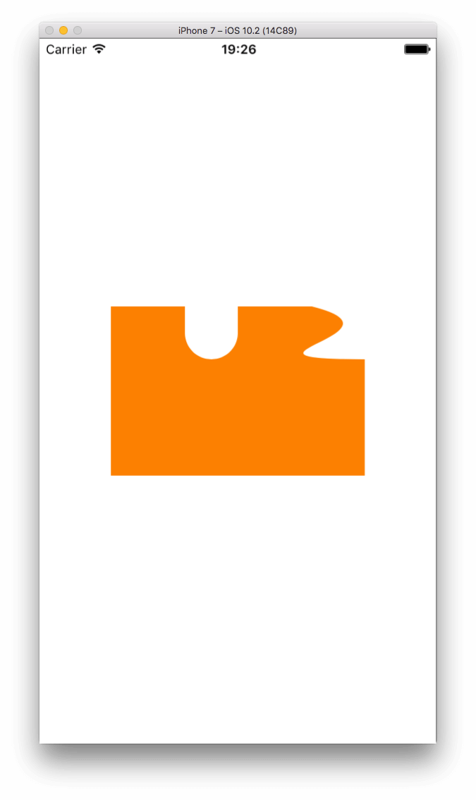
First of all, notice in the code that we use the shape layer as a mask and not as a sublayer. I’m doing that on purpose, just because I want to highlight the final shape. However, the important part is the path creation. As you see, we have a combination of several lines, of an arc and of a curve. We start drawing from the top-left corner (point 0.0, 0.0), and continue in a clockwise direction. Watch the given points carefully to see how the path is drawn step by step.
The new thing above is the addCurve method, which creates the curve we see on the right side of the shape. A curved line is something like that:

The above method that adds a line like that expects three arguments: The final point (endpoint) of the curve, and the two control points that actually define the curvature of the line. Try to change the values of these control points to see how the curve behaves when you modify it. The (painful) truth, though, is that a lot of mathematics lie behind curves, and you can have your first taste here.
Regarding the arc that we create early in the path, there’s nothing new or difficult to mention about. Just remember what we’ve said about drawing arcs, and you’ll see that we followed the recipe “by the book”. All the rest, are just known stuff.
Bonus Material: Using CATextLayer
One of those classes-tools that is less-known, or used at least, is the CATextLayer class. It’s purpose is to allow us to create a layer (like CAShapeLayer) that displays some text. And even though this class has nothing to do with bezier paths or shapes, I really wanted to present it in this post, so I’m providing it here as an additional stuff to read. Think of this part as a small parenthesis in the post.
Every developer displays text in the interface using UILabel objects at 99% of the times (talking about text that cannot be modified). But sometimes using a label might not work, or it becomes messy if there are multiple sublayers added to the layer of the view that contains the label. In that case, the CATextLayer class is what we really need. The additional advantage of this is that we can actually add text layers on top of any view, so we’re not depending just on labels.
Creating and using a CATextlayer is just a matter of configuring a bunch of properties according to the way you want text to be shown. The next code snippet creates such a text layer, which is added as a sublayer to our view’s default layer. See the code, see the results, and then play as much as you want so you get acquainted with it.
func createTextLayer() {
    let textLayer = CATextLayer()
    textLayer.string = "WOW!\nThis is text on a layer!"
    textLayer.foregroundColor = UIColor.white.cgColor
    textLayer.font = UIFont(name: "Avenir", size: 15.0)
    textLayer.fontSize = 15.0
    textLayer.alignmentMode = kCAAlignmentCenter
    textLayer.backgroundColor = UIColor.orange.cgColor
    textLayer.frame = CGRect(x: 0.0, y: self.frame.size.height/2 - 20.0, width: self.frame.size.width, height: 40.0)
    textLayer.contentsScale = UIScreen.main.scale
    self.layer.addSublayer(textLayer)
}
A few things to notice:
- We set the text that we want to show using the string property of the `textLayer` object.
- Even though we specify a font by providing a name and size, it’s also necessary to use the `fontSize` property to specify the font size. It seems that the size given in the font initialisation is not taken into account.
- Text alignment can be set using the `textAlignmentMode` property. There are specific values you can set, and by using the `kCAAlignmentCenter` we align text on the center. More values [here](https://developer.apple.com/reference/quartzcore/catextlayer/horizontal_alignment_modes).
- There’s no option to set the number of lines here, like it happens in a UILabel object. Instead, we can use the “\n” character to break the text in multiple lines according to our preferences. Also, keep in mind to properly set the layer’s frame so text fits properly in it.
- Quite important: Always use the `contentScale` property, as this will make the text be drawn properly on the screen taking its scale value into account. If not used, the result will be pixelated.
Call that method now:
override init(frame: CGRect) {
    ...

    createTextLayer()
}
And here’s what we get back:
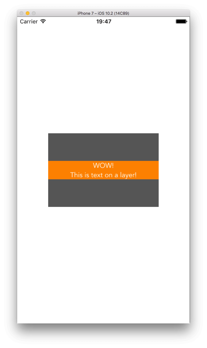
For more information, take a look at the official documentation.
Summary
Getting to the end of this post, I hope that the content of the previous parts was useful and educational for all. By having the basics we met here as a ground, you can go further and create advanced cases where you’ll combine complex paths with custom views or custom shape layers. Actually, how you’ll use everything learnt here is up to you, but now you know; so take advantage of this knowledge and make some magic!


